TECHNICAL SPECIFICATIONS OF SUSPENDED WORK PLATFORM |
|
1.4. A1 SUSPENDED ACCESS EQUIPMENT DEFINITION TECHNICAL FEATURES |
||||||||||||||||||||||||||||||||||||||||
|---|---|---|---|---|---|---|---|---|---|---|---|---|---|---|---|---|---|---|---|---|---|---|---|---|---|---|---|---|---|---|---|---|---|---|---|---|---|---|---|---|
A1 suspended access equipment TS EN 1808 suspension rig safety rules standars 198137 machine safety directive 2004/1108/EC Electro magnetic suppleness, 2004 SS/EC low voltage directive with standarts production requirement of producer's private conditions safety are presented to customer services. |
||||||||||||||||||||||||||||||||||||||||
|
||||||||||||||||||||||||||||||||||||||||
 |
||||||||||||||||||||||||||||||||||||||||
1.5 Structure |
||||||||||||||||||||||||||||||||||||||||
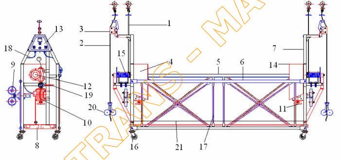
Suspended access equipment that is set on a building temporarily for special aims like painting, cleaning, construction etc. Suspended access equipment is consisted of a platform and on equipment that is assembled to working area before used these are taken away after completed the working. A1 serial GAD companents were introduced. You can see these companents in the part list. |
||||||||||||||||||||||||||||||||||||||||
 |
||||||||||||||||||||||||||||||||||||||||
1.5.1.CARRIER RAPE ( no 01 ) |
||||||||||||||||||||||||||||||||||||||||
Carrier rape that the system. |
||||||||||||||||||||||||||||||||||||||||
1.5.2.SECONDARY WIRE RAPE ( no 02) |
||||||||||||||||||||||||||||||||||||||||
In the case of not able to do its duty of carrier rape and breaking down, secondary wire rape provides safety. |
||||||||||||||||||||||||||||||||||||||||
1.5.3.FALL ARREST DEVICE ( no 03) |
||||||||||||||||||||||||||||||||||||||||
The fall arrest device shall automatically engage in the event of a failure of the suspension wire rape, overspeed on lowering the platform no load condition on the suspension wire or an icline of the platform. |
||||||||||||||||||||||||||||||||||||||||
1.5.4.ACTIVE MECHANISM GROUP ( no 04) |
||||||||||||||||||||||||||||||||||||||||
It provides the working of system, and is a group of motor, reducer, manuel lute and brake. |
||||||||||||||||||||||||||||||||||||||||
1.5.5.REAR GUARD RAIL ( no 05) |
||||||||||||||||||||||||||||||||||||||||
It prevents falling down to the open part of the working area. |
||||||||||||||||||||||||||||||||||||||||
1.5.6.FRONT GUARD RAIL ( no 06) |
||||||||||||||||||||||||||||||||||||||||
It prevents falling down to the front part |
||||||||||||||||||||||||||||||||||||||||
1.5.7.INTERMEDIATE GUARD RAIL ( no 07) |
||||||||||||||||||||||||||||||||||||||||
It prevents the operator to reach the active lute and at the same time it carries lute mechanism. |
||||||||||||||||||||||||||||||||||||||||
1.5.8.PLATFORM - SKIRTING - BOARD ( no 08) |
||||||||||||||||||||||||||||||||||||||||
A working platform that holds system on, provides operator working on. |
||||||||||||||||||||||||||||||||||||||||
1.5.9.GUIDE TAMPONS ( no 09) |
||||||||||||||||||||||||||||||||||||||||
During the working of suspended access equipment, they harden and guide to the wheels while equipment is moving down and up on the building front walls. |
||||||||||||||||||||||||||||||||||||||||
1.5.10.POWER SUPPLY ( no 10) |
||||||||||||||||||||||||||||||||||||||||
Power source of the platform; provides from electric engine. |
||||||||||||||||||||||||||||||||||||||||
1.5.11.HAND- LUTE- WHEEL ( no 11) |
||||||||||||||||||||||||||||||||||||||||
These lutes are used manually when power supply cutting off or setting balance. |
||||||||||||||||||||||||||||||||||||||||
1.5.12.REDUCER ( no 12) |
||||||||||||||||||||||||||||||||||||||||
A gear mechanism that provides movement according to wanted speed and moment, reduces the movement taken from electricity motor in a certain rate. |
||||||||||||||||||||||||||||||||||||||||
1.5.13.ELECTRICITY FRAME ( no 13) |
||||||||||||||||||||||||||||||||||||||||
A frame providing command and control of the system at the same time holds electricity part. |
||||||||||||||||||||||||||||||||||||||||
1.5.14.PROTECTOR ( no 14) |
||||||||||||||||||||||||||||||||||||||||
A polyester protection surrounding motor and reducer mechanism, providing system movement. |
||||||||||||||||||||||||||||||||||||||||
1.5.15.RAPE LIFTING APPLIANCE LUTE (no 15 ) |
||||||||||||||||||||||||||||||||||||||||
A lute that, suspension rapes are fitted an in one or same lines. |
||||||||||||||||||||||||||||||||||||||||
1.5.16.GROUND WHEELS ( no 16 ) |
||||||||||||||||||||||||||||||||||||||||
Wheels that provide suspension rapes are fitted an in one or same lines. |
||||||||||||||||||||||||||||||||||||||||
1.5.17.MIDDLE COLUMNS ( no 17 ) |
||||||||||||||||||||||||||||||||||||||||
Profiles that provide a connection between front guard rail and rear guard rail. |
||||||||||||||||||||||||||||||||||||||||
1.5.18.ELECTRICITY CABLES ( no 18 ) |
||||||||||||||||||||||||||||||||||||||||
Cables that transmit electricity energy. |
||||||||||||||||||||||||||||||||||||||||
1.5.19.MECHANIC BRAKE ARRANGEMENT ( no 19 ) |
||||||||||||||||||||||||||||||||||||||||
A mechanism that assembled between electricity motor and reducer, stops all in the case of cutting thermic because of overloading. |
||||||||||||||||||||||||||||||||||||||||
1.5.20.COUNTER WEIGHTED HEAVINESS, TOE GUARD( no 20 ), ( no21 ) |
||||||||||||||||||||||||||||||||||||||||
An eccentric locked mechanism that provides streching rapes to get worked safety system and toe guard. |
||||||||||||||||||||||||||||||||||||||||
1.6.LIGHTINING |
||||||||||||||||||||||||||||||||||||||||
The lightining system should be used as it is stated below by the user in the case at usage and care of suspended access equipment it is neccessary to provide maximum level of healt and safety conditions, applying below rules and out of daylight. Enough rated lightining should be provided especially in the control and command panel. Provided lightining shouldn't be too much to disturb users eyes. It should be min 100 lux of lightining during care. Whatever the conditions are, operators shouldn't allow reflective of lightining and disturb eyes during command and care. These are the lightened systems of caution and warning in the suspended access equipment : - In the electricity frame; three coloured lamps that shows coming 3 phases - On the electricity frame, 1 lamp to worn overloading. |
||||||||||||||||||||||||||||||||||||||||
1.7. SOUND LEVEL |
||||||||||||||||||||||||||||||||||||||||
Sound level of ADT Equipment: 70 dB (A ) was measured. |
||||||||||||||||||||||||||||||||||||||||
1.8. TERMINOLOGY |
||||||||||||||||||||||||||||||||||||||||
Meaning of terms were explained in 'part- 2 general safety standarts'. Danger area, chosen person, operator expert workers, outhorized service. |
||||||||||||||||||||||||||||||||||||||||
1.9. PAINT |
||||||||||||||||||||||||||||||||||||||||
Painting technics were stated below and varnished electro static dye is used. This dye doesn't harm human and enviroment healty in the case of any touching. To use the dye in a long time, it should be cleaned in a stated way and it is not influenced by chemical substance. If it is cleaned regularly, it can be used in a long way. Vanished electro static dye: Epoxy polyester EW4024 antique silver dye. |
||||||||||||||||||||||||||||||||||||||||
1.10. TRAINING |
||||||||||||||||||||||||||||||||||||||||
To get worked suspended access equipment, it should be used by experienced people. Theoretic and practical training is given to user staff by TRANS-MA construction industry company expert staff. (Look at; Training form) It is not suitable to use suspended access equipment for different aims. Producer company doesn't take any direct or indirect responsibility. Except authorized operator; people who use suspended access equipment should take training. Usage and care handbook given with A1 suspended access equipment should be protected in a accessible way after learned exactly by operator and other authorized people . While the A1 is disassembled, it consists of 5 groups each group weight is given and while transporting these are should be taken into consideration. |
||||||||||||||||||||||||||||||||||||||||
 |
||||||||||||||||||||||||||||||||||||||||
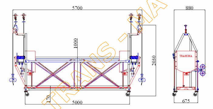
Total Weight : ( Wine rope and 2 x 10 kg, total 200 kg) . |
||||||||||||||||||||||||||||||||||||||||
Assemblied Width: 880 mm, length: 5700 mm, Height :2030 mm |
||||||||||||||||||||||||||||||||||||||||
 |
||||||||||||||||||||||||||||||||||||||||
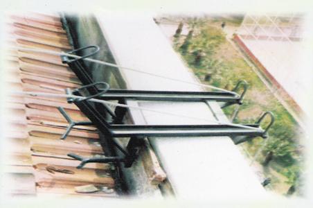
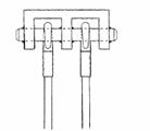
Roof Connection of parapets shown on the picture |
||||||||||||||||||||||||||||||||||||||||
 |
||||||||||||||||||||||||||||||||||||||||
Fasten the equipment tightly with original fastening wire rope and handwifts you given around the turrets and colums in a safely and healthy way. |
||||||||||||||||||||||||||||||||||||||||
1.Wire rope wrapped up on lute |
||||||||||||||||||||||||||||||||||||||||
Open the clip on the wire rope and take it to the top of building in a safety way. Fasten the parapets to the 20 cm thicked wall of the building by the help of given screwsolt should be adjusted according to wire rope assembly dimensions as it was stated in the handbook of setting parapet. After parapet is inserted, insert the hask to the safety steel wire ropes surrounded by column and turret. |
||||||||||||||||||||||||||||||||||||||||
2.Secondary safety wire rope |
||||||||||||||||||||||||||||||||||||||||
It is attached as instructed above that after inserted secondary safety rope, its hook is attached to the safety wire ropes. It should be adjusted that heavires should be 30-40 cm above from the ground. |
||||||||||||||||||||||||||||||||||||||||
3. Hanging systems with wire rope |
||||||||||||||||||||||||||||||||||||||||
 |
||||||||||||||||||||||||||||||||||||||||
Platform should be used with wire rope guides which prevents swinging and loss of stability futher than 40 m. The least holding point should not be more than 40 m futher than working point. Distance between wire rope guides should not be more than 20 m. |
||||||||||||||||||||||||||||||||||||||||
 |
||||||||||||||||||||||||||||||||||||||||
4.Hanging points |
||||||||||||||||||||||||||||||||||||||||
Different hanging points must be assigned for hanging wire rope and secondary hanging rope. |
||||||||||||||||||||||||||||||||||||||||
 |
||||||||||||||||||||||||||||||||||||||||
| 5.Drum coil |
||||||||||||||||||||||||||||||||||||||||
While hanging wire rope is coiling to drum, the distance between max hight of wire and drum edge shall not pass 24 mm(see figure above). |
||||||||||||||||||||||||||||||||||||||||
3.1. WIRE ROPE CONTROL DIMENSIONS DURING THE ASSEMBLY OF SUSPENDED ACCESS EQUIPMENT |
||||||||||||||||||||||||||||||||||||||||
According to type suspended access equipment(1,75 m and 5 m platform) Respect the wire rope dimensions during assembly. |
||||||||||||||||||||||||||||||||||||||||
 |
||||||||||||||||||||||||||||||||||||||||
A1 L ( 5 meter ) Facade hoist's steel wire montage measures |
||||||||||||||||||||||||||||||||||||||||
 |
||||||||||||||||||||||||||||||||||||||||
A1 M ( 3 meter ) Facade hoist's steel wire montage measures |
||||||||||||||||||||||||||||||||||||||||
 |
||||||||||||||||||||||||||||||||||||||||
A1 S ( 1,75 meter ) Facade hoist's steel wire montage measures |
||||||||||||||||||||||||||||||||||||||||
3.2. ELECTRICITY SYSTEM AND CONNECTION OF SUSPENDED ACCESS EQUIPMENT |
||||||||||||||||||||||||||||||||||||||||
3.5.1. ELECTRICITY SYSTEM |
||||||||||||||||||||||||||||||||||||||||
Suspended access equipment works with 380 Volt, 3(+) 1(-) notr 1 grounding blue cable shows notr and yellow cable shows grounding.If there isn't line with 5 it can be attached as combined notr and soil. Romd original wall plug with 5x 16 should be used and be taken energy from fuse group that is between 10-30 ampere. Leakase current relay with 30 MA should be attached to the place electricity taken. It should be kept line with 5 where leakage current relay occurs otherwise it always stops. There is an automatic thermic relay, works in 20 second automatically if electricity cuts down or pulls too current. It should be followed reasons of cutting downs electricity panel is in the IP 55 protection class and has polyester upper protection. Electricity panel should be protected against rain, snow, ice etc. Wall plus under the electricity panel should be suitable to use energy max. 5 amp while welder big breaker, perforater are being used, another wire rope should be used. Electricity cable should be min 5 x 1,5 mm with two breaks. If the distance is long, brea of cable should be increased and it shouldn't be used in a whole part, it should be opened. If electricity welding will be done during working, welder should be attached to component used directly, not cover fromthe machine. |
||||||||||||||||||||||||||||||||||||||||
3.5.2.ELECTRICITY CONNECTION |
||||||||||||||||||||||||||||||||||||||||
Electricity energy should be taken from the middle flor of the building worked. It provides swinging minimum rate. If electricity line won't be able to taken from middle floor and taken from ground floor, cable collector barrel should be putten on the ground. Collecting cables in to the barrel should be supplied easily during working. If the electricity will be taken from the tag or roof floor, electricity cables shouldn't be taken as an optional, except these alternatives, other mechanisms can be used. |
||||||||||||||||||||||||||||||||||||||||
3.7 WORKING OF SUSPENDED ACCESS EQUIPMENT |
||||||||||||||||||||||||||||||||||||||||
Check the assembly of the suspended access equipment in asalety way. Check the connection of building and roof connection with heaviness, wire ropes, hook etc... safely. Check the assembly of of effectivity installation and cables of suspended access equipment in a suitable way. Check the exact and enough quantity of equipment of suspended access. Check Pastering of Safety Belts Make sure that min. 1 person supplying communication and watching out of the platform. Make sure that the last controls are made before working by operators on and out of platform. Check the last time to the surface where suspended access equipment will move (air conditioner, balcony etc) According to these substances adjust the tampons. Take the motor switches on the control panel to 1 by order. Lift the platform up to nearly 50cm height without loading by pushing directions buttons to check the balance. After that ,load the materials. Make sure that the overloading lamps are not warning. Supply the movement by pushing side buttons. |
||||||||||||||||||||||||||||||||||||||||
3.8 STOPPING SUSPENDED ACCESS EQUIPMENT |
||||||||||||||||||||||||||||||||||||||||
Pushing direction buttons supplies the movement of suspended access equipment to stop normal, pushng the buttons is enough. If the direction buttons don't work, push the emergency stop.If the emergency stop doesn't work, take out the switch cable. |
||||||||||||||||||||||||||||||||||||||||
3.11 MISUSING OF SUSPENDED ACCESS EQUIPMENT |
||||||||||||||||||||||||||||||||||||||||
1. Working under hard conditions (for example: magnetic fields, corrosive area etc) 2. Working under special rules (hot wires etc) 3. Carrying passengers from one floor to another. 4. Carrying loading which may cause danger conditions. (malted metal, fragile materials etc) 5. Carrying loading suspended under the platform. 6. In public roads and places where platform can't come down to the safe height. 7. Places having wind pressure that affects loading more than 2 m² surface. 8.Using wireless command system in the suspended access equipment. 9.Trying top reach working place with more than 45° inclimentation. 10.Suspended working platforms to the winches. 11. Using as a silo reaching equipment. 12.Using wires or chain to suspend the platform, 13.Using suspended access equipment underground, 14.Getting work of suspended access equipment with combustion motor, 15.Using suspended access equipment in lightining space 16. Using it out of 10 C° - + 55 C° heat. DEFINITELY FORBIDDEN!!! |
||||||||||||||||||||||||||||||||||||||||
3.12 FORMATION |
||||||||||||||||||||||||||||||||||||||||
User should give training about usage of suspended access equipment to their workers.It is designed according to experiency operators and professional usage. Training is given to operators to get reach them enough usage ability. During procession, it is important to recreate typical working stages in emergency conditions, and practise- user have to give training both operators that works on the equipment and technicion who does the care. |
||||||||||||||||||||||||||||||||||||||||
6.6 EELECTRICAL CIRCUIT |
||||||||||||||||||||||||||||||||||||||||
 |
TRANSMA - MOTORLU ASMA İSKELE - CEPHE PLATFORM İSKELE SİSTEMLERİ - PERSONEL VE YÜK ASANSÖRLERİ - MOBİL İŞ İSKELELERİ - İZMİR - TÜRKİYE 0 232 361 51 33 -361 51 34 2007 © Tüm hakları saklıdır. |