MAST CLIMBING WORK PLATFORM TECHNICAL SPECIFICATIONS
|
| . |
MAST CLIMBING WORK PLATFORM WORKING SYSTEM |
|
|
Platform sizes- width:120cm height:between 100cm-900cm .(portable) |
|
| . |
Max height with top anchor 6m. |
|
| . |
Max height with mast anchored 200 m on condition that using mast ties on every 2 or 3 floors. |
|
| . |
Lifting speed 7 - 17 m/min. |
|
| . |
Available for using 24 hour without stopping by 380 V threephase energy. |
|
| . |
Available for using like material hoist, has different capacities. (300kg-500kg-750 kg 1000kg-1500kg) |
|
| . |
| 2 person enough for assembly .(In assembly phase: necessary for lifting turrets taking into platform and lifting by putting on to each other. In dismantling phase: coming down by dismantling 2-4-6-8-10 turrets and putting on the platform.) |
| . |
| Available for trasportation by towable trailer chassis.(1300cc engine vehicle is enough) |
| . |
MCWP has the big wheels which make available transfering by 1 person even if surface is not flat. |
|
| . |
| MCWP has outriggers which help to fix platform on the ground and increase stability. |
| . |
| Automatically lock in sudden moves by double movement and double electromagnetic brake systems. |
| . |
| Available for using in and out of cabin by remote-control device . |
| . |
| Safety was over and over approved by İzmir Chamber of Mecanical Engineers and some technical universities. |
|
| |
|
| |
MAST CLIMBING WORK PLATFORM TECHNICAL SPECCIFICATIONS |
M1 MCWP relies on TS EN LIFTING PLATFORMS- MAST CLIMBING WORKING PLATFORM STANDARTS, 98/37 EC MACHINE SAFETY DIRECTIVES, 2004 / 108 EC ELECTROMAGNETIC ACCOMODATIONS DIRECTIVES, 2006 / 95 EC LOW VOLTAGE DIRECTIVES, and other related standarts, manufacturer's other special specifications on manufactoring, safety and operation |
| |
|
PRODUCT TYPE - MODEL |
M1 |
|
GENERAL SPECIFICATIONS |
|
Vertical travel speed ( m / sec) |
0,13 |
|
|
İzin verilmez |
|
Outdoor/indoor instalation |
Talimata bakınız |
|
Maximum allowable freestanding height in and out of service (m) |
7,2 |
|
Maximum allowable wind speed during erection (m/s), |
12, 5 |
|
Maximum allowable wind speed during dismantling (m/s), |
15,5 |
|
Maximum allowable wind speed in and out of service (m/s), |
11 |
|
CAPACITY DATA |
|
Maximum platform dimentions (length x width including platform extensions) |
8,20 X 1,20 |
|
Rated load (kg) |
1000 |
|
Maximum lifting height, untied mast (m), |
7,2 |
Maximum lifting height, tied mast (m), |
|
150 |
|
|
7,2 |
|
Top overhang in operation (m), |
2 |
|
Maximum permitted force applied to tools (manually or mechanically assisted) which is to be reacted by the work platform (N), |
500 |
|
Maximum rated load on platform extensions (kg), |
165 |
|
Any load permitted on the work platform during transfer condition |
0 |
|
One outtrigger groud bearing pressure ( N / cm 2 ) |
10,2 |
|
|
PRODUCT TYPE -MODEL |
M1 |
|
DIMENSIONS AND WEIGHTS |
|
Platform section : length × width × height (m), |
1,2 X 1,2 X 0,52 |
|
Platform section : weigh (kg), |
34 |
|
Mast Section : length × width × height (m), |
0,6 X 0,6 X 1,2 |
|
Mast section : weigh (kg), |
39 |
|
Drive unit : length × width × height (m), |
0,8 X 1,2 X 1,6 |
|
Drive Unit : weigh (kg), |
250 |
|
Chassis : length × width × height (m), |
2,5 X 1,47 X 1,2 |
|
Chassis : weigh (kg), |
250 |
|
Outrigger spread and configuration : length × width × height (m), |
0,15 X 0,8 X 0,3 |
|
Base Unit (specified transport configuration) : length × width × height (m), |
2,5 X 1,47 X 1,2 |
|
Base Unit (specified transport configuration) : weigh (kg), |
250 |
|
Minimum area required for installation : length × width |
3,2 X 1,8 |
|
ELECTRICAL DATA |
|
Power lifting machinery (kW), |
3 |
|
Supply voltage / frequency (V/Hz), |
50 |
|
Control Voltage / frequency (V/Hz), |
50 |
|
Maximum starting current (A), |
27 |
|
Maximum Power consumption (kVA), |
4 |
|
Minimum power supply (kVA), |
0,5 |
|
Main power supply fuses and type (A), |
8 13 A TERMİKLİ |
|
Outlets for portable tools voltage and current (V,A) |
380 V 8A |
|
| |
|
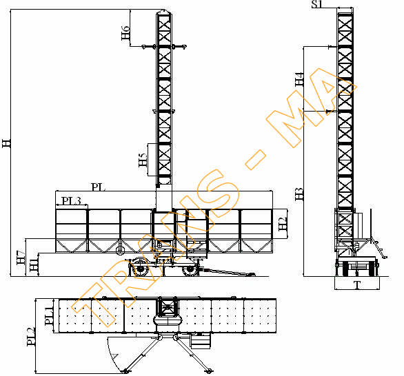
TECHNICAL DIMENSIONS :
H : min 7.2 mt. / max 150mt PL : 8 mt
H1 : 0,85 mt PL1 : 1.2 mt
H2 : 1.1 mt PL2 : max. 2.75 mt
H3 : min 6mt / max.15mt PL3 : 1.2 mt
H4 : 6mt
H5 : 1.2 mt T : 1.65 mt
H6 : 1.3 mt S1 : 0.6 mt
H7 : 1.4 mt A : max 45°
|
| |
3.2.2.FIXING MCWP TO CONSTRUCTIONS
|
|
Above a figure is given as an example to show the MCWP fixing to a construction. Detailed information is given in installing and operating instructions.
|
| |
3.2.3. MCWP Dismantling Instructions |
1. Dismantle the perforated housing sheet.
2. Dismantle the upper ending turret from it's bolts.
3. Dismantle the turrets from their bolts and place them on the platform as balanced weight
according to lifts load capacity.
4.Every 6 meters dismantle the mast ties the you had installed before.
5.Bring dismantled equipment down, upload them, according to loading if needed repeat this step.
6.Repeat step 4 as much as needed.
7.Take down the platform to the lowest position.
8.Turn the electric switch off on the electric console. Unplug it.
9.Unplug the access gate.
10.Dismantle the guardrail bolts and take the guardrails out one by one.
11.Remove the platform panels beginning from the front to rear .
12. Do what is written in Part concerning transport. |
| |
|
| |
|
TRANSMA - MOTORLU ASMA İSKELE - CEPHE PLATFORM İSKELE SİSTEMLERİ - PERSONEL VE YÜK ASANSÖRLERİ - MOBİL İŞ İSKELELERİ - İZMİR - TÜRKİYE 0 232 361 51 33 -361 51 34 2007 © Tüm hakları saklıdır. |
|